|
Name |
IVC1 |
IVC1L |
|||
|
I/O |
I/O point |
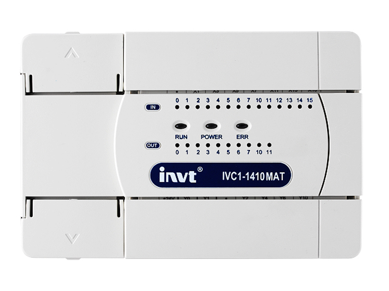
10 inpus/6 outputs 14 inputs/10 outputs 16 inputs/14 outputs 24 inputs/16 outputs 36 inputs/24 outputs 16 inputs/14 outputs/2 analog inputs/1 analog output |
8 inputs/6 outputs 12 inputs/8 outputs 14 inputs/10 outputs 16 inputs/14 outputs 24 inputs/16 outputs 36 inputs/24 outputs 16 inputs/14 outputs/2 analog input/1 analog output |
||
|
Logic max I/O point |
172 |
||||
|
Max special module number |
4 |
||||
|
High speed pulse output |
2×100 kHz, |
3×100 kHz, (3 axes)or 2×200 kHz, 2×20 kHz (4 axes, non-standard) |
|||
|
1PH counting channel |
2×50kHz+4×10kHz |
||||
|
Dual phase counting channel |
1×30kHz+2×5kHz |
||||
|
Max value of high speed counter frequency |
60kHz |
||||
|
Digital filter function |
X0~X7 adopts digital filter, input filter constant can select 0, 2, 4, 8, 16, 32 and 64ms |
||||
|
Max relay output curren |
Resistor load |
2A/1 point;8A/4 point group common terminal;8A/8 point group common terminal |
|||
|
Inductance load |
220Vac, 80VA |
||||
|
Light load |
220Vac, 100W |
||||
|
Max current of transistor output point |
Resistor load |
High speed output pointL 0.3A/1 point; others: 0.3A/1 point;0.8A/4 points;1.6A/8 points The total current increases by 0.1A for every additional 1 pooint above 8points |
|||
|
Inductance load |
High speed output point: 7.2W/24Vdc;others: 12W/24Vdc |
||||
|
Light load |
High speed output point: 0.9W/24Vdc;others:1.5W/24Vdc |
||||
|
Storage |
User program |
16k step (32kByte) |
|||
|
Permanent mainteance at power loss |
Yes |
||||
|
Max number of components maintained at power loss |
Bit component, word component: 2000 |
Bit component: 320, word component: 180 |
|||
|
Hardware support and maintenance time |
EEPROM, permanent storage |
Backup battery, maintenance time is three years |
|||
|
Soft component resource |
Timer |
100ms precision: T0~T209 10ms precision: T210~T251 1ms precision: T252~T255 |
|||
|
Counter |
16-bit up counter: C0~C199 32-bit down counter: C200~C235 32-bit high speed counter: C236~C255 |
||||
|
Data register |
D0~D7999 |
||||
|
Local data register |
V0~V63 |
||||
|
Indexing addressing register |
Z0~Z15 |
||||
|
Special data register |
SD0~SD255 |
||||
|
Auxiliary relay |
M0~M2047 |
||||
|
Local auxiliary relay |
LM0~LM63 |
||||
|
Special auxiliary relay |
SM0~SM255 |
||||
|
State relay |
S0~ S1023 |
||||
|
Interruption resource |
Internal timing interruption |
3 |
|||
|
External interruption |
16 |
||||
|
High speed counter interruption |
6 |
||||
|
Serial interruption |
8 |
||||
|
PTO output completion interruption |
2 |
3 |
|||
|
Power loss interruption |
1 |
||||
|
Regular |
Basic command running time |
0.3μS |
0.2μS |
||
|
Real time clock |
Support (maintain for 100H after power off) |
Support (maintain for three years after power off) |
|||
|
Analog potentiometer |
2/8-bit precision |
Null |
|||
|
Communication |
Communication port |
PORT0:RS232 PORT1:RS485 |
PORT0:RS232 PORT1:RS485 PORT3:RS485 |
||
|
Communication protocol |
Modbus/free port /N:N/program port protocol |
||||
|
Encryption measure |
Set password type |
Upload password, download password, monitor password, sub-program password, formation is prohibited |
|||
|
Upload prohibited |
Support |
||||
|
Application command |
Real-time clock, clock command |
Yes |
|||
|
Date and clock comparison command |
Yes |
||||
|
Floating point number command |
Yes |
||||
|
Positioning command |
Yes |
||||
|
High speed IO command |
Yes |
||||
|
MODBUS and inverter command |
Yes |
||||
|
EEPROM R/W command |
Yes |
No |
|||
|
Control computation command |
Yes |
||||
|
Character string command |
No |
||||
|
Bulk data processing command |
No |
||||
|
Data sheet command |
No |
||||
|
MTBF |
Relay output |
200,000H (fixed to ground, mechanical stress closes to zero, with temp and RH control) |
|||
|
100,000H (fixed to ground, mechanical stress closes to zero, without temp and RH control) |
|||||
|
Transistor output |
300,000H (fixed to ground, mechanical stress closes to zero, with temp and RH control) |
||||
|
150,000H (mechanical stress closes to zero, without temp and RH control) |
|||||
|
Servicelife of output relay contact |
220Vac/15VA/inductive |
1s ON/1s OFF, 3,200,000 times |
|||
|
220Vac/30VA/inductive |
1s ON/1s OFF, 1,200,000 times |
||||
|
220Vac/72VA/inductive |
1s ON/1s OFF, 300,000 times |
||||
|
Ambient environment |
Rated voltage |
100~240VAC (normal operating) |
|||
|
Input voltage range |
85~264VAC (normal operating) |
||||
|
Ambient temp |
-5~55℃ |
||||
|
Storage temp |
-40~70℃ |
||||
|
Withstand voltage |
1 minute of 2830VAC AC current or equivalent DC voltage, no breakdown or arching , leakage current is less than 5mA |
||||
|
Withstand vibration |
Displacement: 3.5mm, acceleration:10m/s2, frequency range:5~150Hz, scan 10 times in X,Y and Z directly respectively |
||||
|
Withstand shock |
Half sine, pulse width:6ms, acceleration:180m/s2 |
||||
|
Protection level |
IP20 |
||||
|
Safety certification |
Design according to IEC61131-2 and UL508 standard, pass CE certification |
||||

Saját fejlesztésű kommunikációs eszközt hoztunk létre IPDRIVE néven, mellyel lehetőség nyílik mindenkinek távoli vezérlések átadására. Pl okosházvezésrlés, távirányítás, bemenetek leolvasása, adagyüjtés, feldolgozás, stb. Jelenleg a készülék webfelületen, lokálisan (LAN) hálozaton konfigurálható, februártól felhő alapon is elérhető a rendszer.
Projekt leírás1.Kis modell, magas konfigurálhatóság capacity and high speed;
2. Erőteéjes pozicionálhatóság, mozgás vezérlés lehetőség
3. Erős, sokoldalú kommunikáció;
4. Ingyenes programozó felület
Cégünk a megkezdte az INVT termékek magyarországi képviseletét
|
Name |
IVC1 |
IVC1L |
|||
|
I/O |
I/O point |
10 inpus/6 outputs 14 inputs/10 outputs 16 inputs/14 outputs 24 inputs/16 outputs 36 inputs/24 outputs 16 inputs/14 outputs/2 analog inputs/1 analog output |
8 inputs/6 outputs 12 inputs/8 outputs 14 inputs/10 outputs 16 inputs/14 outputs 24 inputs/16 outputs 36 inputs/24 outputs 16 inputs/14 outputs/2 analog input/1 analog output |
||
|
Logic max I/O point |
172 |
||||
|
Max special module number |
4 |
||||
|
High speed pulse output |
2×100 kHz, |
3×100 kHz, (3 axes)or 2×200 kHz, 2×20 kHz (4 axes, non-standard) |
|||
|
1PH counting channel |
2×50kHz+4×10kHz |
||||
|
Dual phase counting channel |
1×30kHz+2×5kHz |
||||
|
Max value of high speed counter frequency |
60kHz |
||||
|
Digital filter function |
X0~X7 adopts digital filter, input filter constant can select 0, 2, 4, 8, 16, 32 and 64ms |
||||
|
Max relay output curren |
Resistor load |
2A/1 point;8A/4 point group common terminal;8A/8 point group common terminal |
|||
|
Inductance load |
220Vac, 80VA |
||||
|
Light load |
220Vac, 100W |
||||
|
Max current of transistor output point |
Resistor load |
High speed output pointL 0.3A/1 point; others: 0.3A/1 point;0.8A/4 points;1.6A/8 points The total current increases by 0.1A for every additional 1 pooint above 8points |
|||
|
Inductance load |
High speed output point: 7.2W/24Vdc;others: 12W/24Vdc |
||||
|
Light load |
High speed output point: 0.9W/24Vdc;others:1.5W/24Vdc |
||||
|
Storage |
User program |
16k step (32kByte) |
|||
|
Permanent mainteance at power loss |
Yes |
||||
|
Max number of components maintained at power loss |
Bit component, word component: 2000 |
Bit component: 320, word component: 180 |
|||
|
Hardware support and maintenance time |
EEPROM, permanent storage |
Backup battery, maintenance time is three years |
|||
|
Soft component resource |
Timer |
100ms precision: T0~T209 10ms precision: T210~T251 1ms precision: T252~T255 |
|||
|
Counter |
16-bit up counter: C0~C199 32-bit down counter: C200~C235 32-bit high speed counter: C236~C255 |
||||
|
Data register |
D0~D7999 |
||||
|
Local data register |
V0~V63 |
||||
|
Indexing addressing register |
Z0~Z15 |
||||
|
Special data register |
SD0~SD255 |
||||
|
Auxiliary relay |
M0~M2047 |
||||
|
Local auxiliary relay |
LM0~LM63 |
||||
|
Special auxiliary relay |
SM0~SM255 |
||||
|
State relay |
S0~ S1023 |
||||
|
Interruption resource |
Internal timing interruption |
3 |
|||
|
External interruption |
16 |
||||
|
High speed counter interruption |
6 |
||||
|
Serial interruption |
8 |
||||
|
PTO output completion interruption |
2 |
3 |
|||
|
Power loss interruption |
1 |
||||
|
Regular |
Basic command running time |
0.3μS |
0.2μS |
||
|
Real time clock |
Support (maintain for 100H after power off) |
Support (maintain for three years after power off) |
|||
|
Analog potentiometer |
2/8-bit precision |
Null |
|||
|
Communication |
Communication port |
PORT0:RS232 PORT1:RS485 |
PORT0:RS232 PORT1:RS485 PORT3:RS485 |
||
|
Communication protocol |
Modbus/free port /N:N/program port protocol |
||||
|
Encryption measure |
Set password type |
Upload password, download password, monitor password, sub-program password, formation is prohibited |
|||
|
Upload prohibited |
Support |
||||
|
Application command |
Real-time clock, clock command |
Yes |
|||
|
Date and clock comparison command |
Yes |
||||
|
Floating point number command |
Yes |
||||
|
Positioning command |
Yes |
||||
|
High speed IO command |
Yes |
||||
|
MODBUS and inverter command |
Yes |
||||
|
EEPROM R/W command |
Yes |
No |
|||
|
Control computation command |
Yes |
||||
|
Character string command |
No |
||||
|
Bulk data processing command |
No |
||||
|
Data sheet command |
No |
||||
|
MTBF |
Relay output |
200,000H (fixed to ground, mechanical stress closes to zero, with temp and RH control) |
|||
|
100,000H (fixed to ground, mechanical stress closes to zero, without temp and RH control) |
|||||
|
Transistor output |
300,000H (fixed to ground, mechanical stress closes to zero, with temp and RH control) |
||||
|
150,000H (mechanical stress closes to zero, without temp and RH control) |
|||||
|
Servicelife of output relay contact |
220Vac/15VA/inductive |
1s ON/1s OFF, 3,200,000 times |
|||
|
220Vac/30VA/inductive |
1s ON/1s OFF, 1,200,000 times |
||||
|
220Vac/72VA/inductive |
1s ON/1s OFF, 300,000 times |
||||
|
Ambient environment |
Rated voltage |
100~240VAC (normal operating) |
|||
|
Input voltage range |
85~264VAC (normal operating) |
||||
|
Ambient temp |
-5~55℃ |
||||
|
Storage temp |
-40~70℃ |
||||
|
Withstand voltage |
1 minute of 2830VAC AC current or equivalent DC voltage, no breakdown or arching , leakage current is less than 5mA |
||||
|
Withstand vibration |
Displacement: 3.5mm, acceleration:10m/s2, frequency range:5~150Hz, scan 10 times in X,Y and Z directly respectively |
||||
|
Withstand shock |
Half sine, pulse width:6ms, acceleration:180m/s2 |
||||
|
Protection level |
IP20 |
||||
|
Safety certification |
Design according to IEC61131-2 and UL508 standard, pass CE certification |
||||
Saját fejlesztésű kommunikációs eszközt hoztunk létre IPDRIVE néven, mellyel lehetőség nyílik mindenkinek távoli vezérlések átadására. Pl okosházvezésrlés, távirányítás, bemenetek leolvasása, adagyüjtés, feldolgozás, stb. Jelenleg a készülék webfelületen, lokálisan (LAN) hálozaton konfigurálható, februártól felhő alapon is elérhető a rendszer.
Projekt leírás1.Kis modell, magas konfigurálhatóság capacity and high speed;
2. Erőteéjes pozicionálhatóság, mozgás vezérlés lehetőség
3. Erős, sokoldalú kommunikáció;
4. Ingyenes programozó felület


